Transmission-Line Thermal Inspection from the Field
Ground-based infrared inspection can cover long transmission corridors, but the report still depends on distance, load, focus, and a precise asset reference. These anonymized photographs show the field context without exposing the line identity.
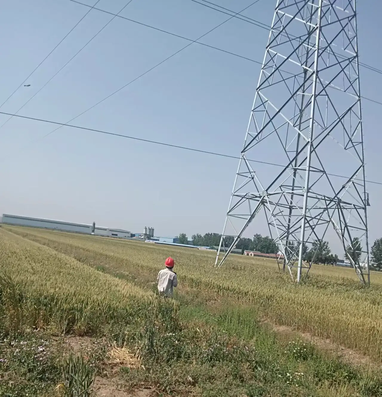
Observed in the supplied photographs: a lattice transmission structure, overhead conductors, an open field setting, and a ground-based inspection activity.
Not disclosed in the supplied material: line voltage, tower number, conductor temperature, load current, defect status, customer name, and exact location.
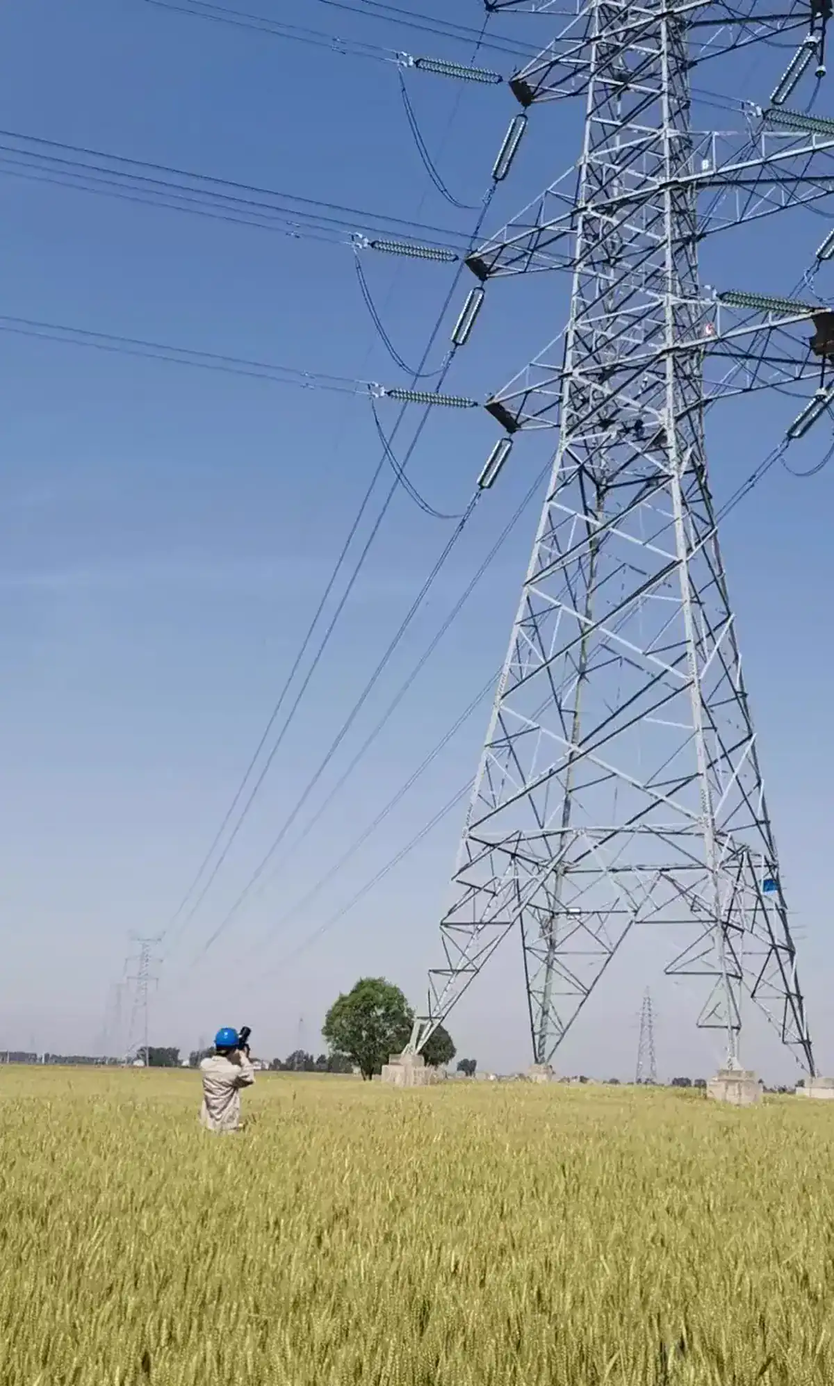
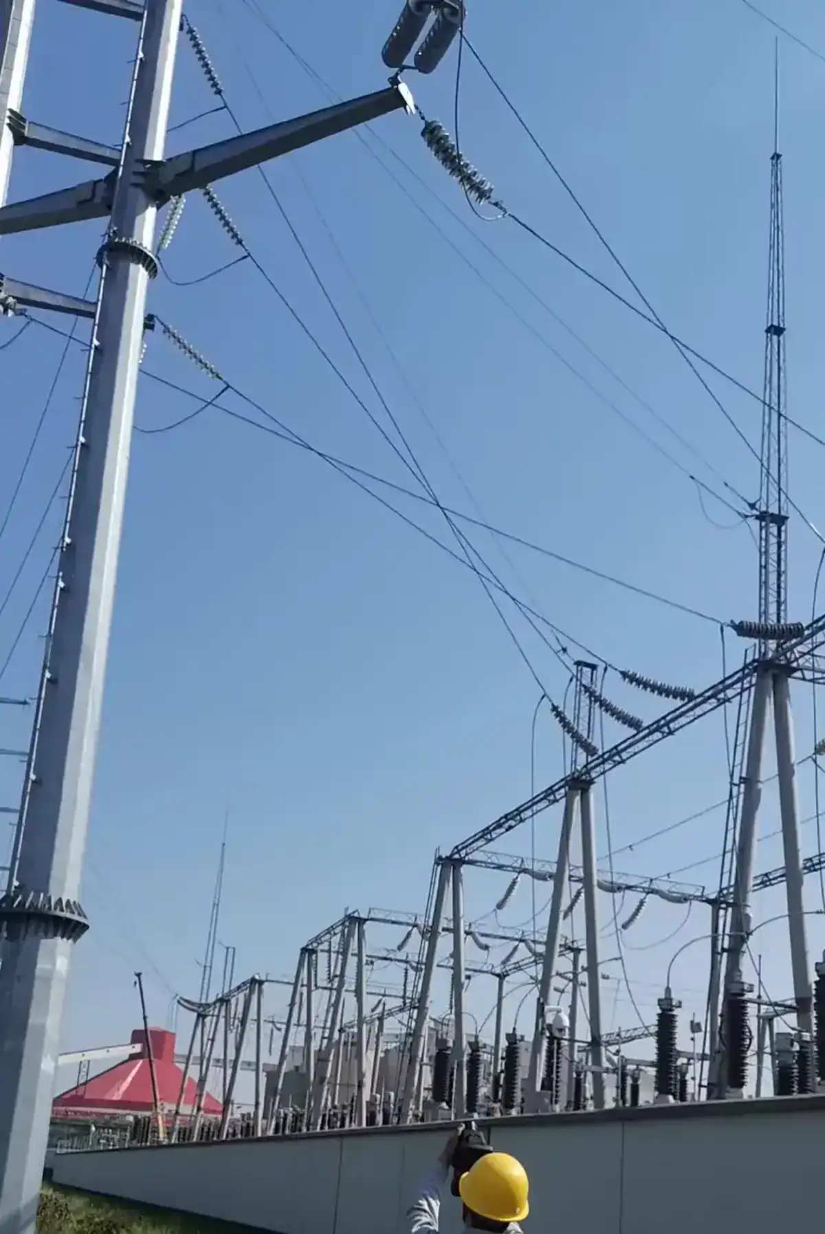
What the images show
The photographs provide useful context for a ground-based survey: the structure is viewed from an open corridor, and the inspection team works without publishing a tower identifier or route name. They do not show a radiometric reading or prove that a conductor, clamp, spacer, or insulator was abnormal.
Ground-based workflow
- Prepare the route and tower list, including safe access and observation points.
- Scan conductors, dead ends, clamps, jumpers, spacers, and insulator connections with adequate focus and pixels on target.
- Record wind, sun, ambient conditions, load information, distance, emissivity, and viewing angle.
- Compare phases and similar structures, then confirm an apparent anomaly from a second angle.
- Attach every image to the correct tower or span reference before issuing a maintenance recommendation.
Long-distance thermography is sensitive to atmospheric attenuation and target size. A clear-looking image is not automatically a reliable temperature measurement.
Evidence limits
The supplied material does not disclose line voltage, load, temperature, tower number, or a confirmed fault. Those details are not disclosed in the supplied material. The correct use of this page is to explain the workflow, not to assign a severity to the pictured line.
See Overhead-Line Conductor Thermal Inspection and thermal camera field-of-view guidance. Related equipment references include the PT II Series and Hammer II Series.
Next step
For route-level planning, share the expected stand-off distance, target size, environmental conditions, and reporting standard through the contact page.
This anonymous field case study uses privacy-processed photographs supplied for publication. It does not identify the customer, facility, city, date, asset number, product model, measured result, or maintenance outcome.